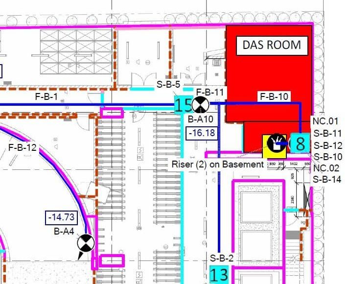
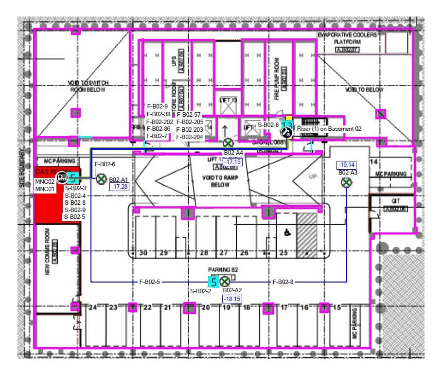
All Distributed Antenna Systems (DAS) require a DAS room for operator equipment and depending on the DAS topology deployed it could require additional locations of various sizes and configurations. We’ll detail some of the considerations of the ‘Main DAS equipment room’ which is typically required regardless of topology, whether active or passive.
This article has been updated for the 2025 iteration of the MCF. Please find our full article on the MCF update here.
Main DAS Room Location
One of the most important and cost impacting considerations is the placement of the DAS room within the overall building. DAS system topology choice is at the mercy of the coaxial cable distance of antennas from the Base Station equipment. As such a DAS room which is further away from the main comms riser may often be the deciding factor between a passive and active system, or the requirement for secondary equipment locations. Both consequences provide additional deployment and operator connection costs. Consequently, the placement of the DAS room can greatly impact the topology of the overall system. Typically, the DAS room is within the basement of a building but locating it on B1 centrally near the riser will produce better outcomes than B5 in a far corner from the communications riser.


On a similar note, the layout of Communications risers and any transitions (doglegs) within the riser can impact the cable length and impact the topology choice for the system. Straight up and down risers allow for shorter cable paths, simpler installation and can minimise the need for active equipment and keep costs down.
Space Requirements for the Main DAS Room
The size of the building largely influences the space requirements for a DAS room and, consequently, the size of the DAS system. The requirements for a 20-story skyscraper would differ from those of a large multi-tower precinct. The space required largely relates back to the number of ‘sectors’ the DAS will require and thus influences the space required by the operator for their subsequent connection. MCF2025 provides for a minimum for 4 racks per operator of 600x600mm dimensions as such to allow for Vodafone, Telstra and Optus would require 12 racks in total within the DAS room.
Typically, WCS would recommend that the minimum DAS room is appropriate for a 3-4 sector site which is most typical of a ~30 story office buildings. More unique sites or precincts require additional planning and consultation with the operators.

The DAS room can ultimately take a variety of physical shapes but needs to support a rack layout for not only the space requirements but also to allow for the doors of racks to open, movement space between the racks and work areas. A lot of which is dictated by the BCA and similar codes.
Most buildings expect to use their DAS for some time, consequently allowing for space within the DAS room to grow and expand is always a wise choice to facilitate future upgrades for additional operator equipment such as 5G.
A DAS with multiple equipment locations or an Active DAS will require fibre to link the various locations, and consequently require a dedicated rack (or more for larger sites) to hold the Fibre termination FOBOTs and the Active DAS Headend. Consequently, for those DAS topologies which require a common headend and fibre distribution, an additional 2 common racks are to be allowed for.
Space within secondary DAS Rooms
There can be valid reasoning for deploying multiple DAS rooms throughout a building, for example, one at the top and one of the bottom to mitigate the loss of the coaxial cable. Historically this was known as a Remote Radio Unit (RRU) topology. The MCF2018 provided some guidance on this, recommending one rack per operator per location. But this is written with the conventional topology of a single sector being at each RRU location, and we often see attempts to wiggle around this and provide short-sighted solutions. MCF2025 updated this for secondary DAS rooms to have the same consideration as primary DAS rooms in their space requirements along with power and cooling considerations.
Infrastructure Requirements for a DAS Room
Cable Tray
Cabling to the DAS room can often be significant and include fibre and coaxial. MCF details to allow for a variety of cable trays to link the DAS room to the main communications riser. Tray around the room to facilitate the various interconnects between the operators and common DAS infrastructure can also lead to a well-maintained and easy-to-shoot layout. There should also be a tray or connection to a tray that ultimately provides a route to the building lead in point for operator transmission, this could be via the MDF room.
Communications Risers
Realistically, somewhere in a Distributed Antenna System will be the use of Coaxial Cable in a vertical orientation traversing up a riser. We understand it can be tempting to have risers move 6 different times up the building, but the reality is Coaxial cable is distanced, limited and rigid with challenging bend radiuses. A riser should be straight up, and down a building, else one risks requiring several Active DAS remotes at significant cost and complexity. Simple is best!
Fibre Connectivity
For DAS systems with multiple equipment rooms, it is common to link the various DAS rooms with single-mode fibre connectivity. The number of cores is variable depending on the site’s configuration.
Cooling
2x6kW cooling capacity be provided within the DAS room to allow for redundancy, this is often split systems in existing buildings, however, development sites may consider alternative ducted solutions to provide similar cooling capacity.
Electrical Considerations
Electrical supply is required within the DAS room to power the three mobile operators’ equipment. Typically, this is in the form of a dedicated DAS Distributed Board within the DAS room with a 100A 3 Phase inbound supply. Any electrical supply required for the room’s cooling solution should be allowed in additional or fed independently elsewhere if ducted.
The individual operators will then install their respective configurations downstream from this main DAS board, typically in the form of 3 Phase 32A outlets.
The ability to switch the DAS board to a generator during power outages (typically scheduled) provides continuous connectivity on site and may be desirable on a site-by-site basis.
Wireless Coverage Solutions have experience deploying Distributed Antenna Systems for properties of all shapes and sizes and intimately understand the requirements for planning an appropriate DAS room and the implications to topology and cost. Don’t hesitate to contact us to discuss your next project.
